Vaillant Arotherm Weather Curve Information
Understanding the heat curve information provided by Vaillant on their Arotherm models of heat pump is vital to making weather compensation work properly.
If you’ve read my “What size heat pump article” you will see why setting up a heat pump in weather comp mode is the best way to run a heat pump.
This recommendation of using weather compensation is then backed up by the performance I’ve been able to get out of my retrofit heat pump.
See how I got on over the first winter heating season here, running it with WC.
First winter with my air source heat pump
How weather compensation works
All weather compensation systems, regardless of which make/model heat pump (or gas boiler) work by adjusting the flow temperature of the water in the radiators or under floor heating based on the outside temperature.
.i.e. you need hotter water in the heating system when it is -3C outside than when it is 10C outside. Hotter water in the heating system equals more heat output from the radiators of under floor heating.
A weather compensation system uses an outdoor temperature sensor to monitor what the latest external temperature is and the system is constantly adjusting the flow temperature of the water in your rads/ufh in response.
The key to weather compensation is finding the curve setting that matches the heat loss of the room/house with the amount of heat put back into the rooms.
- Too high a curve setting and you’ll put too much heat into rooms, which wastes energy.
- Too low a curve setting and the rooms won’t get up to your indoor target temperature.
Where you need to be on the curve is akin to a Goldilocks setting – not too hot, not too cold, but just right.
Once you find the right place on the curve you should get to a situation where there is just enough heat is being put into the house to match the heat lost to the outside.
As can be seen on this 20 hour long run of my heat pump where just enough heat is put into the house and where the flow temp rises and falls in relation to ups and downs of the outside temperature.
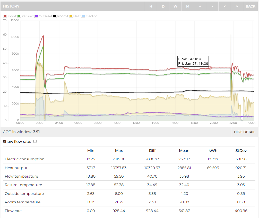
In this example the outside temperature was between 2.8C to 5.8C and the flow temp was between 35C and 37C.
Only subtle changes and fluctuations, but ones that allowed the heat pump continue to run low and slow.
Which is how heat pumps run best. You will get the best performance out of them by finding this sweet spot.
Vaillant diagrams from the manuals
You can find various charts related to weather comp in their manuals, but it can all be a bit cryptic at first glance. So I’m going to try and explain how to read and implement them in this article.
Here is the first snippet from the Vaillant manual.
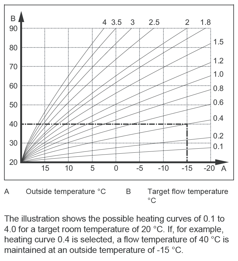
As the text from the manual says, this diagram shows all the possible curves starting at 0.1 rising up to 4.0.
On the Arotherm Sensocomfort controller you choose the curve number in 0.05 increments.
So starting at 0.1, 0.15, 0.2, 0.25, 0.3, 0.35, 0.4, 0.45, 0.5, 0.55, 0.6 and going right up to 3.95 and 4.0.
You can choose the 0.05 versions even though they aren’t shown on any of the graphs.
To get to the menu on the Sensocomfort where you check (and set) the heat curve go to:
- Settings
- Installer Level
- 00 (Access Code) – if left at default
- Installation Configuration
- Circuit 1
- Heat Curve
The VITAL thing to take from this first illustration is that the whole graph shown above ONLY relates to an indoor target temperature of 20C.
If you amend the indoor target room temperature, each degree C that you increase or decrease the target temperature, the target flow temperature changes up or down by around 5C.
- Changing the indoor target temperature by 0.5C adjusts the target flow by 2.5C
- Changing the indoor target temperature by 1C adjusts the target flow by 5C
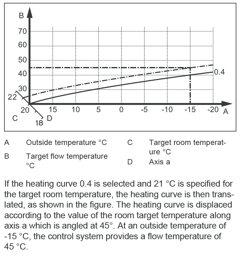
So in essence, the lines on the graph move up or down as you adjust the indoor target temperature.
This next illustration from Vaillant tries to show this.
My heat curve graph scribblings
In an attempt to make sense of all this information I printed out the original graph on a sheet of A4 paper and start scribbling on it.
I first started trying add in the gaps on the graph (0.3, 0.45, 0.5, 0.55) etc.
.i.e. all the gaps around where 40C at -3C would sort of sit (around my installation and other ‘low temp’ installs).
You would hope that most heat pump installations would only need be 1.2 or less on the curve. 1.2 being around 54C at when -3C outside.
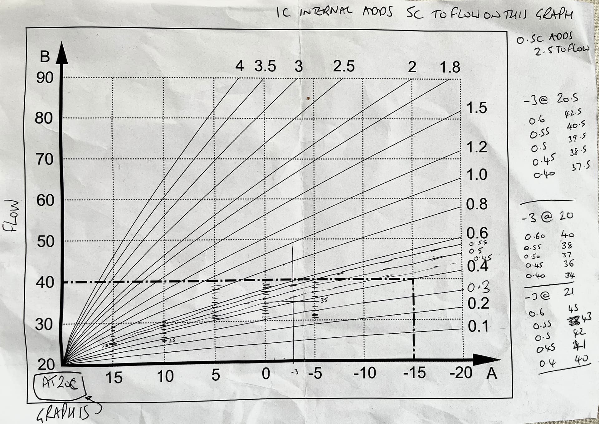
On the right hand side I then started working out tables for different indoor target temperatures based on the 1C indoor / 5C outdoor rule I’d determined.
Curve info in table format
After drawing lots of lines on the graph it became clear that it was going to be too difficult to get all the info I needed on the graph.
So I took to creating a spreadsheet and started to chart out data points in tables.
Below are my attempts at showing many of the curves in table format for different target indoor temperatures.
- Top Left in Yellow is the room target temperature
- Blue across the top are the outdoor temperature points from the graph
- Green down the left are the curve settings
- The main body of the table in white contains the flow temperatures for a given outdoor temp / curve setting
19C Indoor Target Temperature

19.5C Indoor Target Temperature

20C Indoor Target Temperature
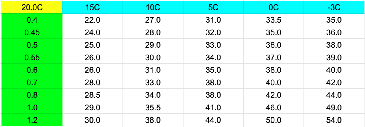
20.5C Indoor Target Temperature
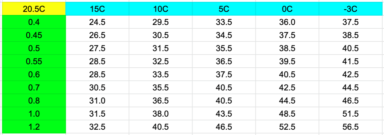
21C Indoor Target Temperature
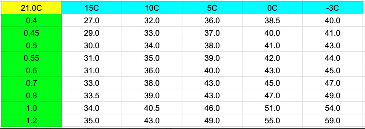
How to use the tables and curve info
I think there are two methods to use the heat curves
- Use Design Temperatures
- Heat Geek (turn down until you are cold!)
Use Design Temperatures
All MCS approved heat pump installations must have a full heat loss survey that produces a target design.
The target design is a combination of ‘flow temperature’, ‘design outside temperature’ (DOT) and ‘indoor target temperature’.
Note: heat loss calcs and design outside temperatures are all discussed heavily in both the “What size heat pump?” and “First winter with our air source heat pump” articles if you need more information.
Where you are in the country will heavily affect your Design Outside Temperature (DOT). i.e. it gets colder in the highlands of Scotland in deep winter than it does in London for example.
The heat loss of your house and size of your radiator/under floor will dictate your target flow temp.
Your installer should provide all these calculations and paperwork to you.
For my installation, my target flow temperature is 40C at -3C (my design outside temperature) and my indoor target temperature is 20C.
So if we go back to the 20C chart listed above, look at the -3C column on the very right hand side, come down until we hit 40C, we’ll land upon the row showing the 0.6 curve (left hand column). So we’d choose that.
If my system design was 45C at -3C, then we’d go for 0.8 on the curve as a starting point.
The system will adjust the flow temperature of the water in the radiators to the points along the curve depending on the outdoor temperature.
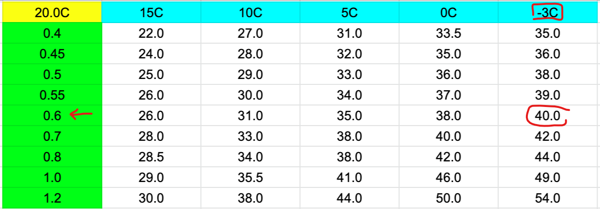
So going back to the graph, we can highlight those figures (40C at -3 for 20C indoors) to show how it looks on the graph if we chose curve 0.6 when 20C indoors.
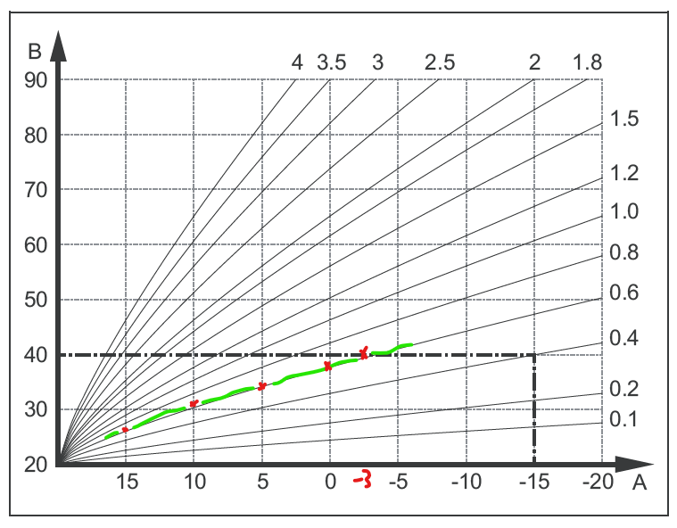
Note: there is a bit of rounding up and rounding down of some of the figures in the tables I created to hit whole numbers. So just pick the closest to your design temperatures as a starting point.
Once you’ve tried this curve selection for a while and you get an idea whether you’re too hot or too cold you can turn things down or up as required.
Heat Geek (turn down until you are cold!)
This was advice that Heat Geek gave me just after installing our system.
It may sound funny and a bit simple, but it does work!
Once the weather turns cold outside, turn down the heat curve a little bit each day. Keep an eye on how the house feels.
When you get to the day where things start to feel a bit too chilly, turn it back up one notch. And that’s it. Once you’ve found this point you’re good to go.
Sometimes your system may perform better than the heat loss calcs, sometimes a little worse.
By using the “turn down until you’re cold” method you are sort of ignoring the design and going with how you feel instead.
End of the day, comfort is king.
Note: There is nothing you can do to harm the system by changing the heat curve as all you’re doing it adjusting the temperature of the water in the rads/UFH.
Remember: the lower the temperature of the water the better performance (or better COP) you will get.
But if you do get cold, just dial the curve back up a little.
Indoor Target Temperature Really Matters
You can hopefully see from the different temperature tables above why the indoor target temperature is so important in the equation.
Those that can tolerate a house at 19C will benefit from much lower flow temperatures than those that like it toasty at 21C.
The working flow temperatures would be 10C lower across the board for those that want it cooler inside, which would make massive difference in the performance achieved by the system across the whole year.
Remember, the lower the flow temperature the higher the performance (COP).
If we look back at the figures from the Vaillant brochure we can see the difference that 10C of flow would make on performance across the year (SCOP).

I do find the metric of indoor target temperature to get lost somewhat along the line when folks are comparing COP/SCOP figures of their heat pumps.
Especially as it makes such a difference to performance (19C to 21C) for example.
If you are interesting in comparing performance figures of heat pumps, then be sure to head over to heatpumpmonitor.org which is part of the Open Energy Monitor project.
My heat pump is up there along with 40+ others at the last count.
Room Controls
I’m not going to go into a massive amount of detail, but the “Room Temp Mod” setting can have an influence.
The Room Temp Mod setting on the Sensocomfort relates to what role your room controller plays in adjusting the flow temperature of the system.
You can find the “Room Temp Mod” option in the same ‘Circuit’ screen as when setting the heat curve.
Room Temp Mod has 3 options to choose from.
- Inactive = Pure WC (the Sensocomfort room stat is nothing but a display)
- Active = WC and Room Influence (depending how far away room temp is from indoor target the system can adjust the flow temp, i.e. increase it if room needs a little more heat)
- Expanded = WC and Room influence, but also acts as on/off stat switching the heating off if room temp is exceeded.
I mention these options in case you see the flow temp of your system not exactly matching the heat curve graphs.
You may have got your controller set to ‘Active’ or ‘Expanded’ and could be asserting some influence over the flow temperature.
Ideally we’d run Inactive (Pure WC), but you may find the other options suit your installation better for one reason or another.
Again, nothing wrong with changing these settings if you understand them.

Referral information and free credit offer
If you find the content of this website useful and are thinking of joining Octopus Energy, please consider using my referral code or ‘buy me a coffee’ to help support running costs of the website.
Using this referral code will gift you £50 of free Octopus Energy credit after signup: https://share.octopus.energy/linen-pearl-869
If you would like to ‘buy me a coffee’ to show support, please use this link: http://buymeacoffee.com/SVHgIbUYM
If you’re considering owning part of a wind farm through Ripple Energy, get £25 of free credit (if investing more than £1000) using my Ripple referral link.
Energy Stats can also be found on Twitter. Please follow us @energystatsuk for daily Agile tariff pricing graphs and summaries.
And we have also started posting the same graphs over on Mastodon. You can find us here: https://mastodonapp.uk/@energystatsuk
Note: The current and past performance of energy pricing is not necessarily a guide to the future.


